During the lab, we will be using AND, OR, XOR, and NOT logic gates. Logic gates are built with transistors. For the first part of the lab, you will create your own NOT gate using a transistor and resistors. For the remaining parts of the lab, you will be using pre-built logic gates made with transistors packaged inside a chip. When multiple transistors are built into a single chip, that is called an integrated circuit (IC). We will be using four ICs that each have several Logic Gates inside of them: the 7404, 7408, 7432, and 7486 chips.
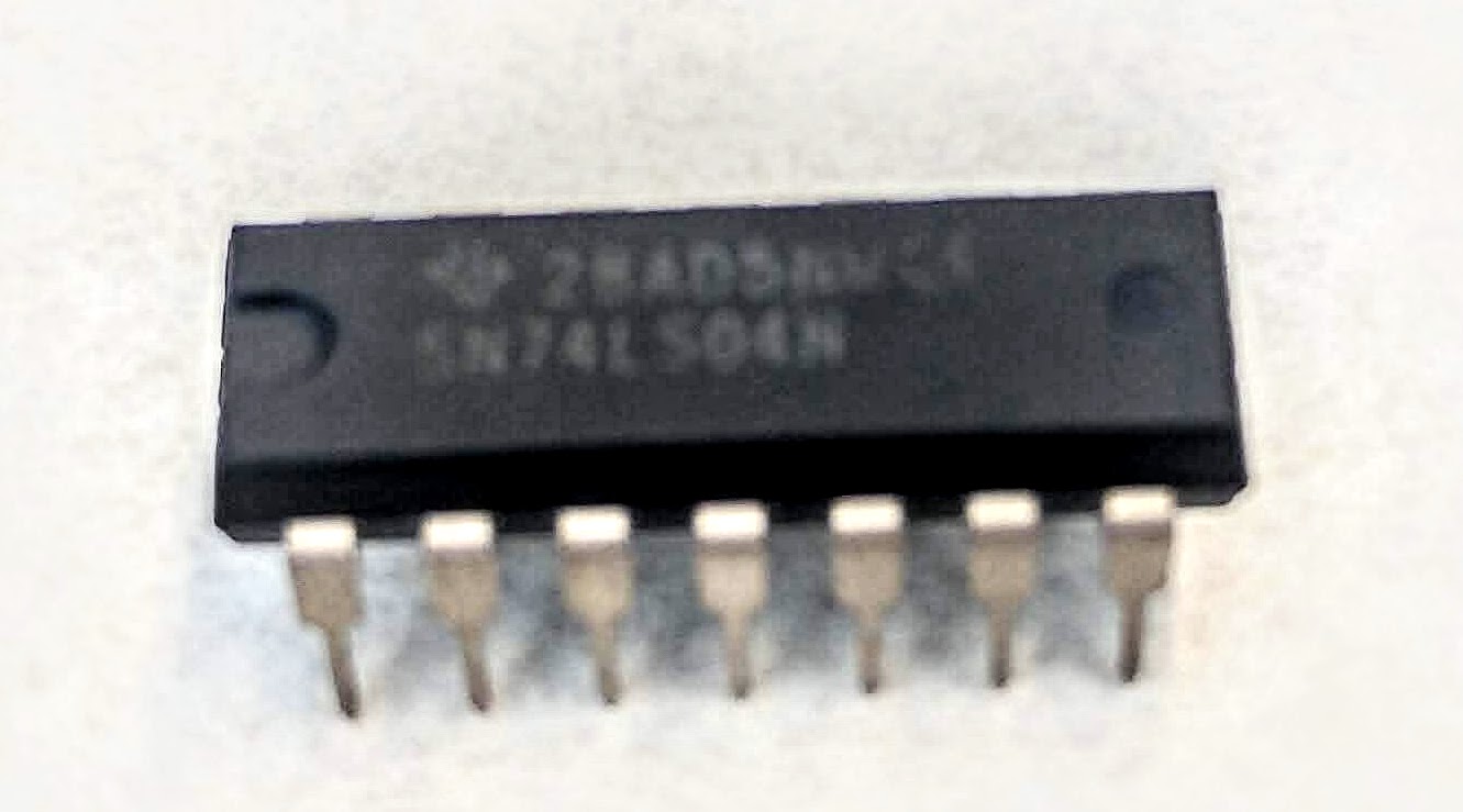
These chips look like the image below. They have 14 metal legs (called pins) - 7 on each side.
Finding the chips in your kit: The chips are added to the kit by the bookstore, so they aren't listed on the kit "contents." They should come in your kit in a group of 4 or 8 chips with the pins pushed inside black or pink styrofoam to keep the pins from bending. They may be in a dark ziplock bag. Don't confuse them with the other two chips in your kit that look similar but have 16 pins. If you didn't purchase your kit from the bookstore and are missing the chips, you can purchase them separately from the bookstore using this link.
Labeling: These chips are often labeled with additional letters. For example, instead of 7404, you may see it labeled as 74LS04 or SN74LS04. The numbers are the important part of the label.
Number of chips: If your kit has eight of these logic chips instead of four, it just means that you have a backup of each chip.
Missing chips: If you can't find them, look again. You can ask your instructor to help you find them in your kit over Zoom. If you still can't find them, contact the bookstore.
Purchasing chips separately: Sometimes the bookstore also sells the chips separately from the kit.
If a chip breaks: If one of your chips breaks or isn't working correctly, see if you have a backup chip in your kit. If not, contact your instructor for help or purchase more from the bookstore using this link.
Take a look at the "connection diagram" for each of these four chips, in the datasheets below.
Next to the connection diagram, you should also see a "function table" (Truth Table) for each, with H (HIGH) for True and L (LOW) for False.